Rule
As introduced in general concepts, a rule is a tool that you can use to monitor your assets and be notified of abnormal situations or events. You can configure a rule to send email or notify your operators in the dashboard. Examples of use cases include: a fire is detected in a building, a lift has broken down, or when a machine is overdue for maintenance. Rule is the tool you can use to configure these notifications.
A rule in Senfi comprises of:
- Inputs - Metric & Tag values
- Conditions
- Result - True or False, a Boolean value
- Actions - Do something when Result changes. e.g. send notification email
- Rule execution options - Configures when a Rule is evaluated
Inputs are evaluated by Conditions to generate a single boolean Result. When value of Result changes, Actions, such as email and dashboard alerts, are executed. Rule execution options allows you to configure how the Rule is executed. e.g: how often the Rule is evaluated, when to execute Actions etc.
Inputs --> Conditions --> Result
Result Changed --> Actions
Contents
Example
- Input: iot_weighingscale_v1.battery_level
- Condition: < 20
- Action: Email reminder to replace battery
- Rule execution option: Immediately (means evaluate this rule whenever there is any incoming measurement)
Inputs, Conditions and Result
Before adding a Rule, you should already have an event or situation that you wish to be notified about. The event or situation should be one that can be detected by monitoring data received by Senfi.
Select, as Inputs, the Metrics and Measurements from which the event or situation can be detected from. Then, construct the set of Conditions that will evaluate to true when event or situation occurs. The result of said Conditions is the Result of the Rule.
Actions
Whenever Result changes (from true to false and vice versa), Actions may be executed. Actions includes sending an email, request to a webhook or triggering an alert in the dashboard.
Content of Actions
Depending on the Action, different content options are available. Some examples is the title & body of an email, and body content for webhook request. You will be able to describe the event or situation that has happened to the recipient of the notification in the content of an Action
To further aid you in describing the event, you can embed the value or tag of an Input metric in the content of an Action. You can also embed the Rule's Name, Description and Severity in the content of an Action.
To embed:
- metric's value, use ${<measurement_code>.<metric_code>}. e.g: ${iot_temperature_sensor_v1.temperature}
- metric's tag, use ${<measurement_code>.<tag>}. e.g: ${iot_temperature_sensor_v1.site_id}
- Rule's name, use ${NAME}.
- Rule's description, use ${DESCRIPTION}.
- Rule's severity, use ${SEVERITY}.
Take a look at this more detailed example.
Rule execution options
By setting Evaluate Type to Immediate or Polling, you can choose to execute a Rule when new values are received for any Input Measurements, or periodically, regardless of whether any Input Measurements have changed.
If Rule is set to run periodically (Polling), you must specify how often a Rule is executed by setting Intervals in seconds.
Misc
Name and Description
A Rule also has a Name and Description. The Name and Description allows you to describe the event or situation that the Rule detects, such that recipients of the Rule's alert/notification knows exactly what happened and is able to react to it accordingly.
- The Rule's Name is displayed in the CMS' list of Rules.
- The Rule's Name and Description is displayed in the Dashboard.
You can also embed the value or tag of Input metrics in the Description. The syntax is the same as embedding in the content of an Action, as described here.
Description is also the default content of an Action. You can describe the event or situation once in the Description, and reuse the information in all the Actions of the Rule.
Severity
You can also set the severity of the Rule. Default severity is Critical. Severity allows users of the Dashboard to filter Alerts by severity and attend to more severe Alerts first.
Detailed Example
The event that you would like to be notified about is potential fire in a building. There are temperature sensors throughout the building. When a reading from any temperature sensor exceeds 60°C, a fire has probably broken out near the sensor. You would like to be notified by email of such an occurrence.
- The Input in this example would be the metric and measurement that readings from temperature sensor is sent to. e.g: iot_temperature_sensor_v1.temperature
- Condition is iot_temperature_sensor_v1.temperature > 60
- Action is email, with body text:
- "Potential fire detected in room: ${iot_temperature_sensor_v1.room}. Temperature in the room is ${iot_temperature_sensor_v1.temperature}°C"
With the above Rule configured, when iot_temperature_sensor.temperature goes from 59 to 61, an email will be sent with the body text:
- "Potential fire detected in room: #03-00. Temperature in the room is 61°C"
Note: "room" is a Tag of the iot_temperature_sensor_v1 measurement that indicates which room the sensor is in.
Constructing Condition
This section will guide you to construct a condition using the Rule Editor when adding/editing a Rule in the CMS. The objective here is to tell Senfi how to detect the event or situation that you wish to be notified of.
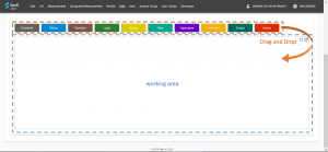
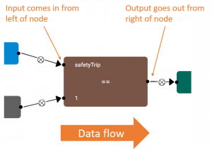
The Rule Editor is a graph based "Drag and Drop" editor. Each node in the Editor represents either an Input, Data Transformation, Logic, or an Action. Arrows are used to link the nodes and control the flow of data between nodes.
Arrows coming into the left of a node indicates the node's input,
and arrows going out the right of a node indicates the node's output.
The graph must always start from Input nodes and ends in the Result or Action nodes (Data originates from Input nodes, is transformed by Data Transformation, Logic nodes, and is consumed by Result & Action nodes).
- Input nodes
- Metric - outputs the value/s of a metric. can be set to output the last known value, or a range of historical values
- Logic Nodes
- Compare - comparison operators. e.g. <, >=, ==, !=
- Logic - perform "AND" or "OR" between 2 or more boolean values
- Data Transformation nodes
- Filter - used to filter a range of values and output a subset number of values. Can only be used after a Metric node in "Range of Value" mode and before an Aggregate
- Aggregate - used to aggregates a range of values into a single value. E.g. sum, average, median. Can only be used after a Metric node in "Range of Value" mode
- Function - value-wise transformation. Transform each value, e.g ABS, Floor, Round etc. Can be used after a Metric node and before a Compare node. Outputs the same number of values as its input.
- Result node
- Result - Result node. Must have 1 and only 1 node. Specifies the Result of a Rule
- Action nodes
- Action - Action node. Input must always be from the "Result" node. Can have 0 or more "Action" nodes. Instructs Senfi to do something when Result changes.
Basic Steps
- Drag a node above working area into the working area to create a node.
- Create "Metric" nodes, one for each Input metric.
- Select the correct measurement and metric for each "Metric" node. Read: how to configure a node
- (Optional) If you need to compare metric value against a constant value, use the "Constant" node.
- Create "Operator" and "Logic" nodes to construct necessary logic
- logic graph should output a single boolean (true or false) value
- output from "Metric" node must go to input of a "Operator" node.
- "Operator" and "Logic" nodes can be nested.
- You can attach more than 2 inputs to a "Logic" node
- Create a "Result" node and attach output of logic graph as its input
- Create "Action" nodes, one for each desired Action and attach output of "Result" node as its input
- Save when done
Example
Example 1: A simple Rule detecting when a Lift has tripped (safetyTrip == 1).
Example 2: Detects when a Lift tripped (safetyTrip == 1), AND passengers are trapped in the Lift (load > 0)
Working with historical values
When historical values is required to detect an event, the "Range", "Filter" and "Aggregate" nodes are needed.
By default, a "Metric" node will output the Last Known value of the metric. To obtain historical values of a metric, attach the output of "Metric" node to the input of a "Range" node. The output of the "Range" node will be historical values from the metric.
The configuration options of the "Range" node allows you to change the range of historical values to output. E.g: You can configure it to output metric values from 1 hour ago till now, or the last 10 received metric values.
After obtaining the list of historical values, you can:
- Filter the list using the "Filter" node.
- Transform each value in the list using the "Function" node.
The "Filter" and "Function" nodes can be nested.
Finally, the list of historical values must be aggregated using the "Aggregate" node before its output can be used by a "Logic" or "Operator" node.
Example using historical values
The example above detects when a Lift is stopped at Level 2 for over a minute.
Configuring Nodes
Each node contains attributes & options which you can modify. To modify the attributes of a node, move your mouse over the node and click on the "Gear" button that appears near the top right corner of the node (Beside the "X" button). A window will popup to allow you to configure the node.
Aggregate node
This section explains what each of the options for "Aggregate" node does.
- sum
- the sum of all input values
- count
- the number of input values
- average
- the average of input values
- median
- the median value of input values
- max
- the largest value
- min
- the smallest value
- mode
- the value that appears most often
- range
- the difference between the largest and smallest value (max - min)
- stddev
- standard deviation
- percentile
- percentile. This option accepts an additional "Percentile Value" parameter.
- every
- outputs true if every value fulfills the condition. This option accepts an additional "Condition" parameter.
- any
- outputs true if at least 1 value fulfills the condition. This option accepts an additional "Condition" parameter.
Function node
This section explains what each of the options in "Function" node does.
- abs
- absolute value
- round
- round to nearest integer
- ceil
- round up
- floor
- round down
- map
- This option accepts an additional "function" parameter. Using the custom "function" parameter, transforms each input value


